Loop detector problems are among the most frustrating maintenance challenges in parking operations because the failures are often intermittent, difficult to reproduce consistently, and can have multiple contributing causes. A gate that randomly stays open, randomly won’t open, or triggers for objects that aren’t there may have a failing detector, a deteriorating loop, a sensitivity setting issue, or an interference problem — and distinguishing between these requires a systematic approach.
This guide provides a systematic troubleshooting framework for the most common loop detector failure modes in parking facilities.
Understanding the Loop Detection System
Before troubleshooting, understand the complete system. An inductive loop detection system consists of:
- The loop wire: Copper wire embedded in the pavement, forming a coil (typically rectangular)
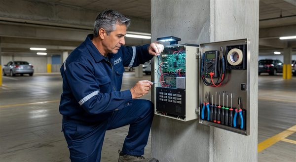
- The lead-in cable: The cable running from the loop in the pavement to the detector electronics (usually in the gate cabinet)
- The detector unit: Electronics that measure loop inductance and output a detection signal when inductance changes
- The controlled device: The gate, counter, or access control system that receives the detection signal
Problems can occur in any of these four components. Effective troubleshooting identifies which component is failing before attempting repair.
Failure Mode Identification
Failure Mode 1: Gate Won’t Open for Vehicles (Missed Detections)
Symptoms: Vehicles stop at the gate; the gate doesn’t open automatically. Driver must press help button or use ticket manually.
Diagnostic sequence:
Step 1 — Test the detector sensitivity setting. Access the detector unit in the gate cabinet. Most detectors have a sensitivity adjustment (potentiometer or DIP switch). Test by placing a coin on the cabinet top and sliding it slowly toward the loop area — if the gate opens with just the coin (a very small metal object), sensitivity is set too high. If sensitivity appears normal and the problem persists, continue.
Step 2 — Check the loop resistance. Using a multimeter, measure resistance across the two loop terminals on the detector. Normal resistance for a properly functioning loop varies by wire gauge and loop size but is typically 0.5–5 ohms for most commercial installations. Resistance approaching open circuit (infinite) indicates a loop wire break.
Step 3 — Check the loop inductance. Use an inductance meter or a specialized loop tester. Inductance should match the baseline value for the loop (noted at installation, or measured when the system was known to be working). Significant inductance deviation suggests loop geometry change (damaged or shifted wire) or significant contamination.
Step 4 — Identify interference. Nearby equipment that cycles on and off (HVAC equipment, elevators, other gates) can cause interference that desensitizes the detector during their operating cycle. Observe whether missed detections correlate with the operation of nearby equipment.
Failure Mode 2: Gate Opens Without a Vehicle (False Detections)
Symptoms: Gate opens spontaneously; gate opens for pedestrians, shopping carts, or small objects; gate cycles rapidly with no vehicles present.
Diagnostic sequence:
Step 1 — Check sensitivity setting. Over-sensitive detectors trigger for small metal objects, nearby vehicles in adjacent lanes, or even significant metal on a pedestrian. Reduce sensitivity and retest.
Step 2 — Check for nearby interference. Active interference from nearby sources (large motors, welding equipment, radio transmitters near the operating frequency) causes false triggers. Identify whether false detections are random or correlated with any pattern.
Step 3 — Check the lead-in cable. Damaged insulation on the lead-in cable (where it exits the pavement and runs to the cabinet) allows moisture to bridge between the conductors, simulating a detection event. Inspect the cable where it exits the pavement surface for damage.
Step 4 — Evaluate loop geometry. If the loop wire has been disturbed by pavement repairs, plow damage, or thermal expansion, its geometry has changed. Changed geometry shifts the loop’s inductance baseline, potentially causing the detector to trigger at calibrated thresholds that no longer match the altered loop.
Failure Mode 3: Intermittent Detection
Symptoms: The gate sometimes works correctly and sometimes doesn’t — failures don’t follow a consistent pattern.
Diagnostic sequence:
Step 1 — Document the pattern. Note exactly when failures occur: time of day, weather conditions, temperature, whether any other equipment is operating nearby. Intermittent failures with weather correlation suggest moisture in the system; failures correlated with temperature suggest a component at the edge of its thermal specification.
Step 2 — Inspect all connections. Loose connections at the detector terminals, corroded terminals in a junction box, or damaged wire insulation that makes intermittent contact are common causes of intermittent detection. Clean and re-torque all accessible connections.
Step 3 — Test under the conditions that produce failures. If failures only occur in wet weather, test during or after rain. If temperature-related, test at the temperature range where failures occur. Intermittent problems diagnosed only in ideal conditions often remain unsolved.
Step 4 — Measure loop resistance and inductance over time. A loop that shows normal resistance when warm but increased resistance when cold has a marginal connection or wire failure developing.
Tools Required for Loop Detector Troubleshooting
Multimeter with resistance measurement: Essential for checking loop continuity and resistance. A basic $30–$50 multimeter is adequate for this measurement.
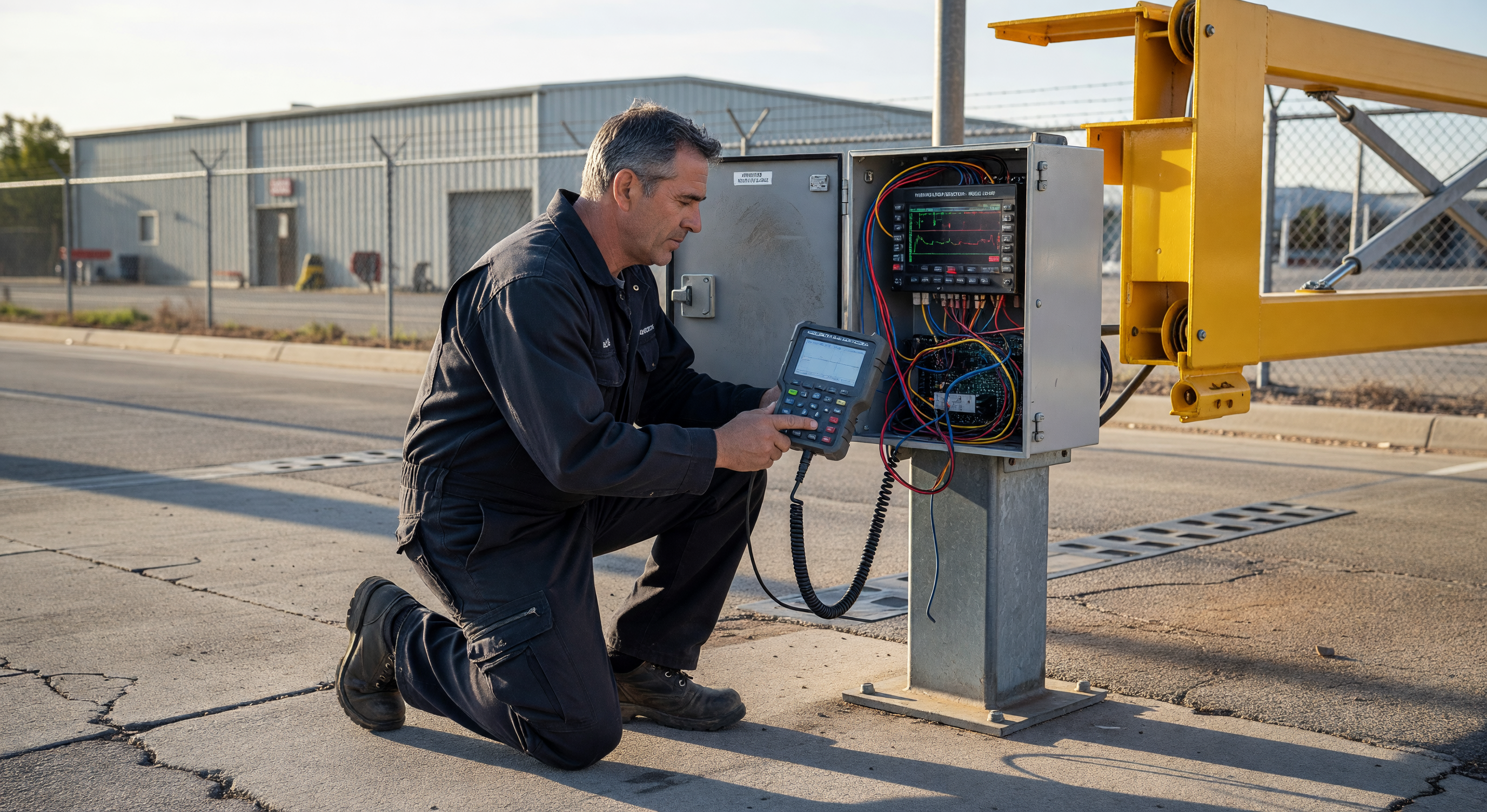
Loop tester or inductance meter: Measures loop inductance and quality factor — provides more diagnostic information than resistance alone. Loop testers designed for traffic and parking applications are available for $200–$600.
Oscilloscope (optional): For diagnosing interference patterns and detector signal quality. Useful for facilities with persistent mysterious false detections; not required for standard troubleshooting.
Laptop with detector configuration software: Some modern detector units have USB or serial configuration interfaces allowing detailed parameter adjustment and diagnostic data retrieval.
Common Repair Options
Detector Unit Replacement
If the diagnostic process identifies the detector electronics as the failure point (the loop tests healthy but the detector doesn’t respond correctly), replacement is straightforward: disconnect the loop leads and output wiring, remove the old unit, and install a new unit with the same or compatible footprint.
Most detector mounting formats are standardized (plug-in card or DIN rail). Universal detector cards are available for most common slot configurations at $100–$300 per channel.
Loop Repair
Loop wire breaks can sometimes be repaired without full loop replacement:
- Break at the lead-in exit point: The most common location for breaks. If the break is accessible (within a few inches of the pavement surface), a splice with appropriate wire nuts and waterproof sealant can restore continuity.
- Break within the pavement: Generally not repairable without cutting the pavement to access the wire. If the break location can be localized (using a time-domain reflectometer), targeted pavement repair may be less extensive than full loop replacement.
Full Loop Replacement
When the loop wire is too damaged to repair, the pavement-cut loop must be replaced. This requires:
- Saw-cutting the existing loop path (may reuse existing cuts if still serviceable)
- Removing the old wire
- Installing new loop wire (14 AWG solid copper wire, THWN insulation, is standard)
- Sealing the cut with loop sealant
- Reconnecting and calibrating the detector
Full loop replacement in a single lane takes 2–4 hours for a prepared crew and typically requires a lane closure.
Frequently Asked Questions
How long should an inductive loop last before replacement? In good pavement conditions, loops last 10–20 years. In northern climates with freeze-thaw cycling and road salt, expect 7–12 years. High-traffic installations with heavy truck traffic see shorter loop life due to pavement stress.
Can I install a temporary loop without cutting pavement? Rubber-encased surface loops that lay on top of the pavement without cuts are available. They’re not appropriate for permanent high-traffic installations (vehicles run over them constantly), but they’re useful for temporary applications, event parking, or as a diagnostic tool to verify that the detector is functional while suspecting a bad pavement loop.
Why does my loop detector trigger when a large truck in an adjacent lane stops? This is crosstalk — the large metal mass of a truck in an adjacent lane changes the inductance of a nearby loop. The solution is sensitivity reduction to the point where the adjacent-lane vehicle no longer triggers the detector while still detecting vehicles in the correct lane. Some sites require loop geometry modification or additional shielding if the lanes are very close.
What does the Q factor on a loop detector represent? The Q factor (quality factor) measures the efficiency of the resonant circuit formed by the loop and the detector’s tuning capacitor. Low Q indicates high resistance in the system — degraded wire connections, damaged insulation, or poor pavement sealing around the loop. Healthy loops typically have Q factors of 5–30 depending on loop size and wire gauge.
Key Takeaway
Loop detector troubleshooting is most efficient when it follows the diagnostic sequence: establish whether the problem is in the detector, the loop wire, the lead-in cable, or interference — before attempting any repairs. Replacing a detector when the problem is actually a deteriorating loop wire solves nothing. Systematic isolation of the failure component saves significant time and material cost.